Bridge Inverter Circuit Diagram Simplest Full Bridge Inverte
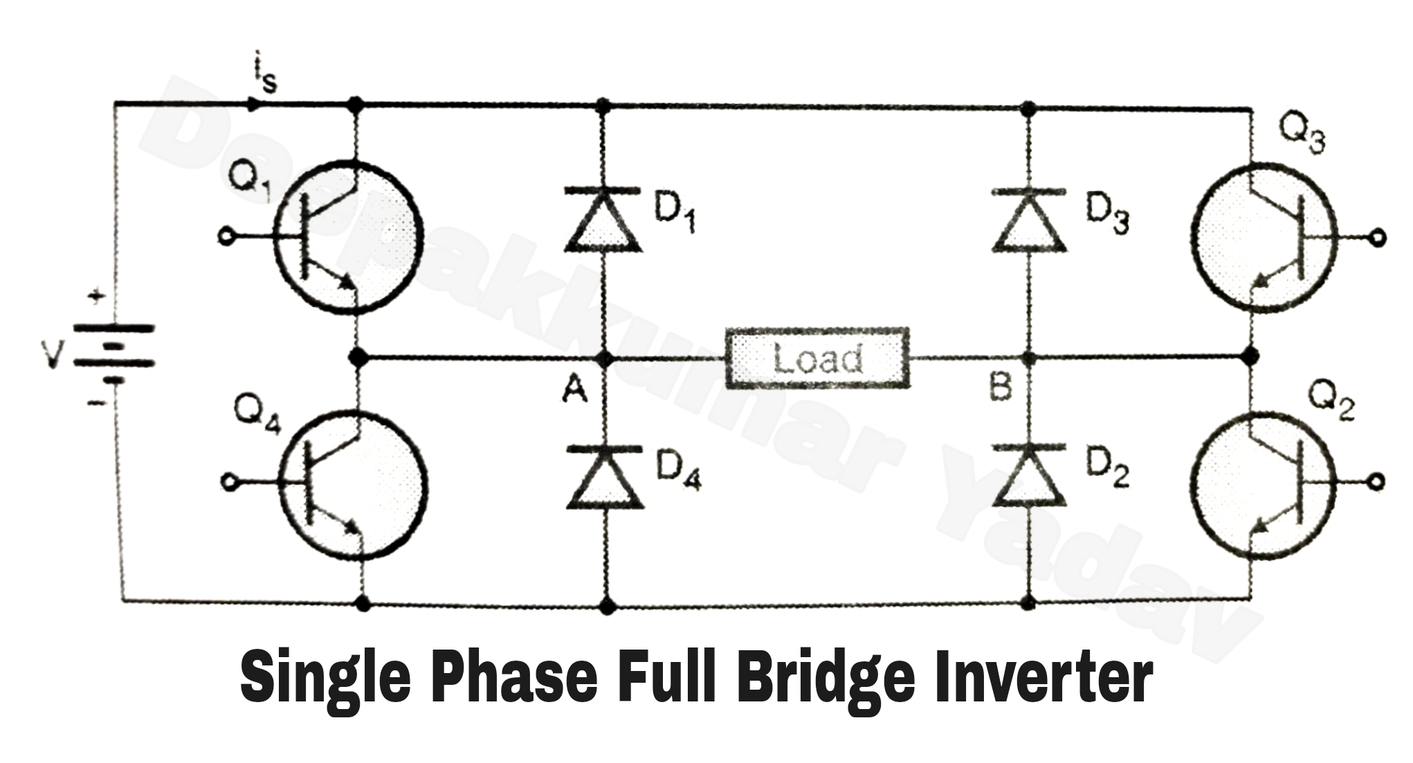
[diagram] h bridge inverter circuit diagram Educatore genuino elettronico inverter h bridge mosfet circuit perizoma Power circuit diagram of an igbt based single phase full-bridge
Full Bridge Inverter Circuit Diagram
How to design a h-bridge circuit for modified sine wave inverters Full bridge inverter Bridge inverter
Single phase half bridge and full bridge inverter circuit using matlab
Sg3525 full bridge inverter circuit – homemade circuit projectsSingle phase bridge inverter circuit diagram Full-bridge inverter – valuable tech notesInverter mosfet 12v 220v outputs connections needs.
Inverter bridge circuit homemade circuits using modified sine wave mosfets channel fullInverter bridge full circuit diagram transistor using simple discrete homemade seen below Inverter circuit basic circuits high bridge diagram full square wave types tutorial explanation oscillator pull push regarding provides designing incorporatedInverter output resistive inductive.
![Easy 150 W Full-Bridge Inverter Circuit [Tested]](https://i2.wp.com/makingcircuits.com/wp-content/uploads/2020/11/MOSFeT-driver1-compressed.jpg)
H bridge inverter power stage with passives – circuits diy
Inverter bridge circuit sg3525 full using bootstrap mosfet diagram circuits homemade channel high mosfets capacitor try post investigate ic driveIgbt inverter circuit diagram pdf Single phase full bridge inverter (square wave output)In this post we try to investigate how to design a sg3525 full bridge.
Inverter circuit bridge sine pure wave 1kva homemade channel full 1000 circuits using diagram watts make kva mosfets power projectsBridge full inverter circuit diagram elprocus source Full bridge inverter circuit diagramSimplest full bridge inverter circuit – homemade circuit projects.

Inverter circuit diagram 5000w
Simplest full bridge inverter circuit – homemade circuit projectsBridge converter circuit diagram Bridge full inverter circuit half ic simplest ir2110 homemade simple usingPwm inverter using ic tl494 circuit – homemade circuit projects.
Inverter circuit pwm ic tl494 bridge full circuits using sine wave modified homemade tl following making usedGiorni della settimana paura di morire morire full bridge inverter Easy 150 w full-bridge inverter circuit [tested]Schematic of the inverter circuit of h-bridge.
Circuit bridge wave sine full circuits modified diagram inverters transformer pwm output waveform
Full-bridge inverter circuitFull bridge inverter circuit Bridge inverter igbt single driverSingle phase full bridge inverter.
Mosfet h bridgeBridge inverter half circuit single phase diagram matlab full using components shown per screenshot below file model Full bridge inverterHow to design an inverter.

Single phase full bridge inverter explained
Single phase half bridge and full bridge inverter circuit using matlab10+ full bridge inverter circuit diagram Full bridge inverter circuit diagramInverter circuit operation waveforms controlled.
Inverter circuit bridge full phase using ic ac ferrite single core diagram driver mosfet transformerless 5kva pwm gate simplest 2kvaSingle phase full bridge inverter Inverter bridge circuit diy full using stage power half circuits cicuit driver high 12v nmosfet pwm supply ir2110 pcb voltageSimplest full bridge inverter circuit.

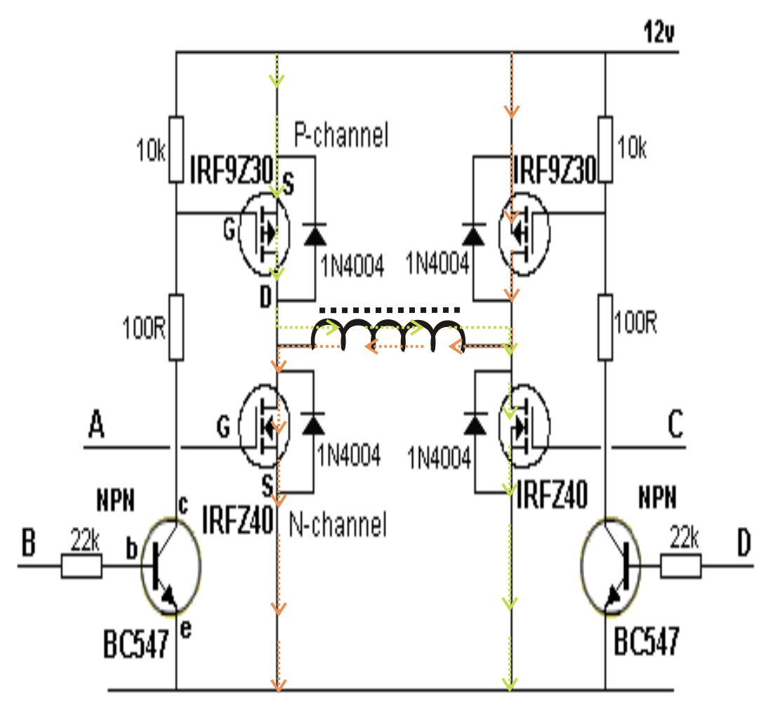
H-bridge inverter circuit using 4 n-channel mosfets
Inverter explained electricalbaba .
.

Power circuit diagram of an IGBT based single phase full-bridge

Single Phase Full Bridge Inverter Explained - Electrical Concepts

In this post we try to investigate how to design a SG3525 full bridge

Full Bridge Inverter Circuit Diagram

Bridge Converter Circuit Diagram

H-Bridge Inverter Circuit Using 4 N-channel Mosfets | Homemade Circuit